
Home » Electrical Installation Reference
Installation Reference for Ag Ventilation Systems
Wire sizing, conduit fill, PVC bending, and Ohm’s Law in one place. Built for electricians, ag installers, and extension agents spec’ing or installing ventilation systems.
1. Motor Amps & Wire Sizing Chart
Full-load amperage for single-phase and three-phase motors. Cross-reference with wire sizing table to select minimum conductor gauge.
Use FLA (full-load amps) to select wire gauge and breaker size. For continuous-duty motor circuits, multiply FLA × 1.25 per NEC 430.22. Wire sizing reflects max amps at 60°F for copper and aluminum conductors.
Single phase — 115V / 230V 1PH FLA
| HP | 115V (A) | 230V (A) |
|---|---|---|
| 0.33 | 7.2 | 3.6 |
| 0.50 | 9.8 | 4.9 |
| 0.75 | 13.8 | 6.9 |
| 1.00 | 16 | 8 |
| 1.50 | 20 | 10 |
| 2.00 | 24 | 12 |
| 3.00 | 17 | |
| 5.00 | 28 | |
| 7.50 | 40 | |
| 10.00 | 50 |
Wire sizing — max amps (60° wire)
| Gauge (AWG/kcmil) | Copper Max Amps | Aluminum Max Amps |
|---|---|---|
| 14 | 15 | |
| 12 | 20 | 15 |
| 10 | 30 | 25 |
| 8 | 40 | 35 |
| 6 | 55 | 40 |
| 4 | 70 | 55 |
| 3 | 85 | 65 |
| 2 | 95 | 75 |
| 1 | 110 | 85 |
| 1/0 | 125 | 100 |
| 2/0 | 145 | 115 |
| 3/0 | 165 | 130 |
| 4/0 | 195 | 150 |
| 250 | 215 | 170 |
| 300 | 240 | 195 |
| 350 | 260 | 210 |
| 400 | 211 | 224 |
| 500 | 273 | 260 |
| 600 | 350 | 285 |
| 700 | 385 | 315 |
3 phase — 208V / 230V / 460V FLA
| HP | 208V (A) | 230V (A) | 460V (A) |
|---|---|---|---|
| 0.50 | 2.4 | 2.2 | 1.1 |
| 0.75 | 3.5 | 3.2 | 1.6 |
| 1.00 | 4.6 | 4.2 | 2.1 |
| 1.50 | 6.6 | 6 | 3 |
| 2.00 | 7.5 | 6.8 | 3.4 |
| 3.00 | 10.6 | 9.6 | 4.8 |
| 5.00 | 16.7 | 15.52 | 7.6 |
| 7.50 | 24.2 | 22 | 11 |
| 10.00 | 30.8 | 28 | 14 |
| 15 | 46.2 | 42 | 21 |
| 20.00 | 59.4 | 54 | 27 |
| 25.00 | 74.8 | 68 | 34 |
| 30.00 | 88 | 80 | 40 |
| 50.00 | 143 | 130 | 65 |
| 75.00 | 211 | 192 | 96 |
| 100.00 | 273 | 248 | 124 |
2. Conduit Fill Chart
Maximum fill is 40% of conduit interior area for 3 or more conductors (NEC Chapter 9, Table 1). Use the wire count columns below to quickly select conduit size.
Values show the maximum number of THHN conductors before the conduit is full (or at max heat load). Maximum fill is 40% of conduit interior area for 3 or more conductors per NEC Chapter 9, Table 1.
Max conductors in a conduit
| Gauge (AWG) | 0.5 in | 0.75 in | 1 in | 1.5 in | 2 in | 2.5 in | 3 in |
|---|---|---|---|---|---|---|---|
| 14 | 11 | 21 | 34 | 82 | 135 | 193 | 299 |
| 12 | 8 | 15 | 25 | 59 | 99 | 141 | 218 |
| 10 | 5 | 9 | 15 | 37 | 62 | 89 | 137 |
| 8 | 3 | 5 | 9 | 21 | 36 | 51 | 79 |
| 6 | 1 | 4 | 6 | 15 | 26 | 37 | 57 |
| 4 | 1 | 2 | 4 | 9 | 16 | 22 | 35 |
| 2 | 1 | 1 | 3 | 8 | 11 | 16 | 25 |
| 1 | 1 | 1 | 1 | 5 | 8 | 12 | 18 |
| 1/0 | 1 | 1 | 1 | 4 | 7 | 10 | 15 |
| 2/0 | 1 | 1 | 3 | 6 | 8 | 13 | |
| 3/0 | 1 | 1 | 3 | 5 | 7 | 11 | |
| 4/0 | 1 | 1 | 2 | 4 | 6 | 9 |
4–6 conductors → × 0.80 | 7–9 → × 0.70 | 10–20 → × 0.50
3. PVC conduit bending & heating tips
Step-by-step for field bending PVC in ag environments. Cold bending cracks the conduit wall, heat first, every time.
These steps apply to Schedule 40 and 80 PVC conduit. In barns and wet ag locations, PVC is often preferred over EMT for its corrosion resistance — but it requires proper heating technique to bend cleanly.
Measure and mark the bend point
Mark the bend start with a grease pencil or tape. For a 90° stub-up, subtract the gain for your conduit size from your measurement (e.g. approximately 5″ gain for 1/2″ conduit). Account for gain before cutting.
Heat the section evenly
Use a heat gun or infrared blanket. Rotate the conduit continuously to heat a 6–8″ section uniformly. PVC is ready when it becomes soft and pliable without whitening or bubbling.
Bend to angle and hold
Bend against a form or mechanical conduit bender. Apply steady, even pressure — do not kink. Hold the bend until the PVC has cooled and set (30–60 seconds).
Fill conduit with dry sand before bending to prevent flattening on tight radii.
Verify and cool fully
Check angle with a protractor or bender level. Allow full cooling before threading wire. PVC disturbed while still warm will spring back slightly, account for this on stub-up bends.
Expansion and support in ag environments
PVC expands approximately 0.038″ per 10°F per 10 feet of run. In barns with significant temperature swings, install expansion couplings every 25–30 feet. Support horizontal runs every 3 feet for 1/2″–1″ conduit.
4. Ohm's law quick reference
Use when troubleshooting motor circuits or calculating expected current draw from a known load.
Plumbing terminology equivalents
VOLTS
= Water pressure
High-pressure washers burst low-pressure pipes. High voltage overwhelms undersized circuits the same way.
AMPS
= Flow rate (GPM)
How bulky the electricity is, the volume of flow moving through the wire at any moment.
OHMS
= Pipe resistance (drag)
A skinny hose filling a pool takes forever. Higher resistance makes it harder for current to pass through.
The key takeaway: Amps can’t be changed directly. To reduce amps, you either reduce the voltage (don’t push as hard) or increase the resistance (squeeze the pipe tighter). Watts is like paying the sewer bill, billed in kW instead of gallons.
Formulas
V = I × R
Solve for voltage
I = V ÷ R
Solve for current (amps)
R = V ÷ I
Solve for resistance (Ω)
P = V × I
Solve for power (watts)
Watts power triangle
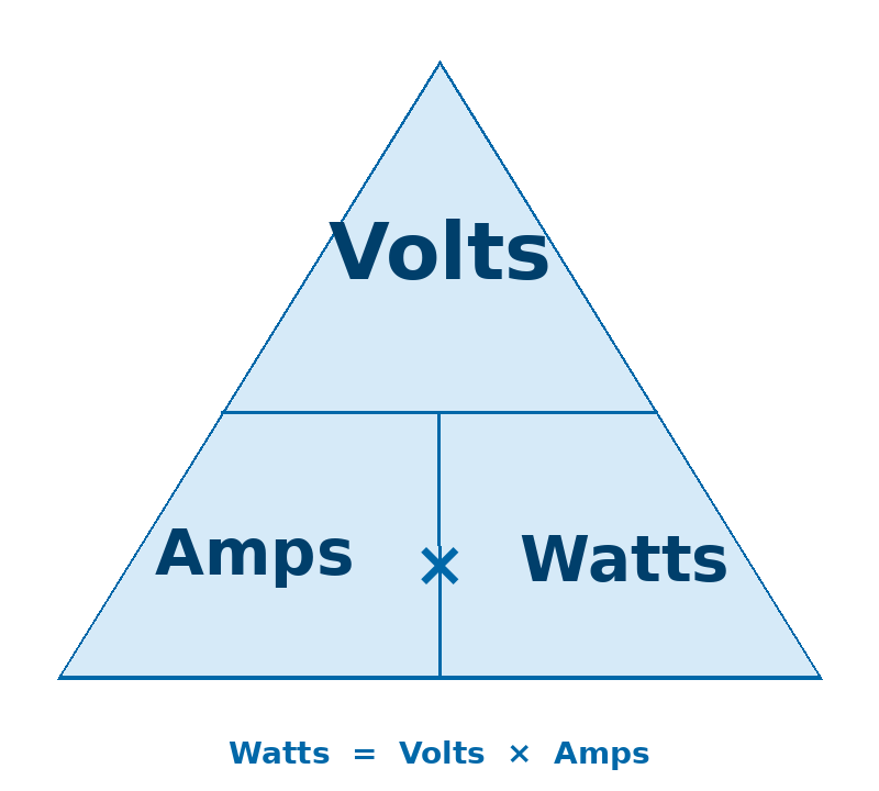
- Cover Watts →
Volts × Amps - Cover Volts →
Watts ÷ Amps - Cover Amps →
Watts ÷ Volts
1,000 watts = 1 kW. Your power bill is measured in kWh (kilowatts running for one hour).
Worked example — 1 HP, 230V single-phase motor circuit
Power draw: P = 230 × 8.0 = 1,840 W (1.84 kW)
Expected R: R = 230 ÷ 8.0 = 28.75 Ω
High reading (>35Ω) → check for bad connection or undersized wire.
Low reading (<20Ω) → possible winding fault; check motor insulation.
V = Voltage (volts) | I = Current (amps) | R = Resistance (ohms) | P = Power (watts)
Download as PDF
Get a print-ready version of all four charts — formatted for field use and toolbox reference.
Spec'ing a ventilation system?
AutoVent’s team works directly with installers and electricians on system design, motor selection, and wiring layout.